Designing a foldable quadcopter
2024/05/01Context
For a while I've been wanting to design a quadcopter with arms that fold inwards to aid with transporting to/from test flights and also has a large airframe for additional avionics and payload capability. This blog post outlines my thought process whilst I designed the quadcopter in CAD before building it out of carbon fibre and 3D printed parts.
Avionics
One thing to get out the way before designing the quadcopter were the avionics. I needed a drone which could carry at least a 3kg payload, meaning the motors chosen had to have a fairly high thrust output. The flight computer would be running ArduPilot which allows for easy autonomous missions.
- Flight controller: Matek H743 Mini V3
- PDB: Matek PDB HEX
- ESC: T-Motor Velox V45A 4-in-1 ESC
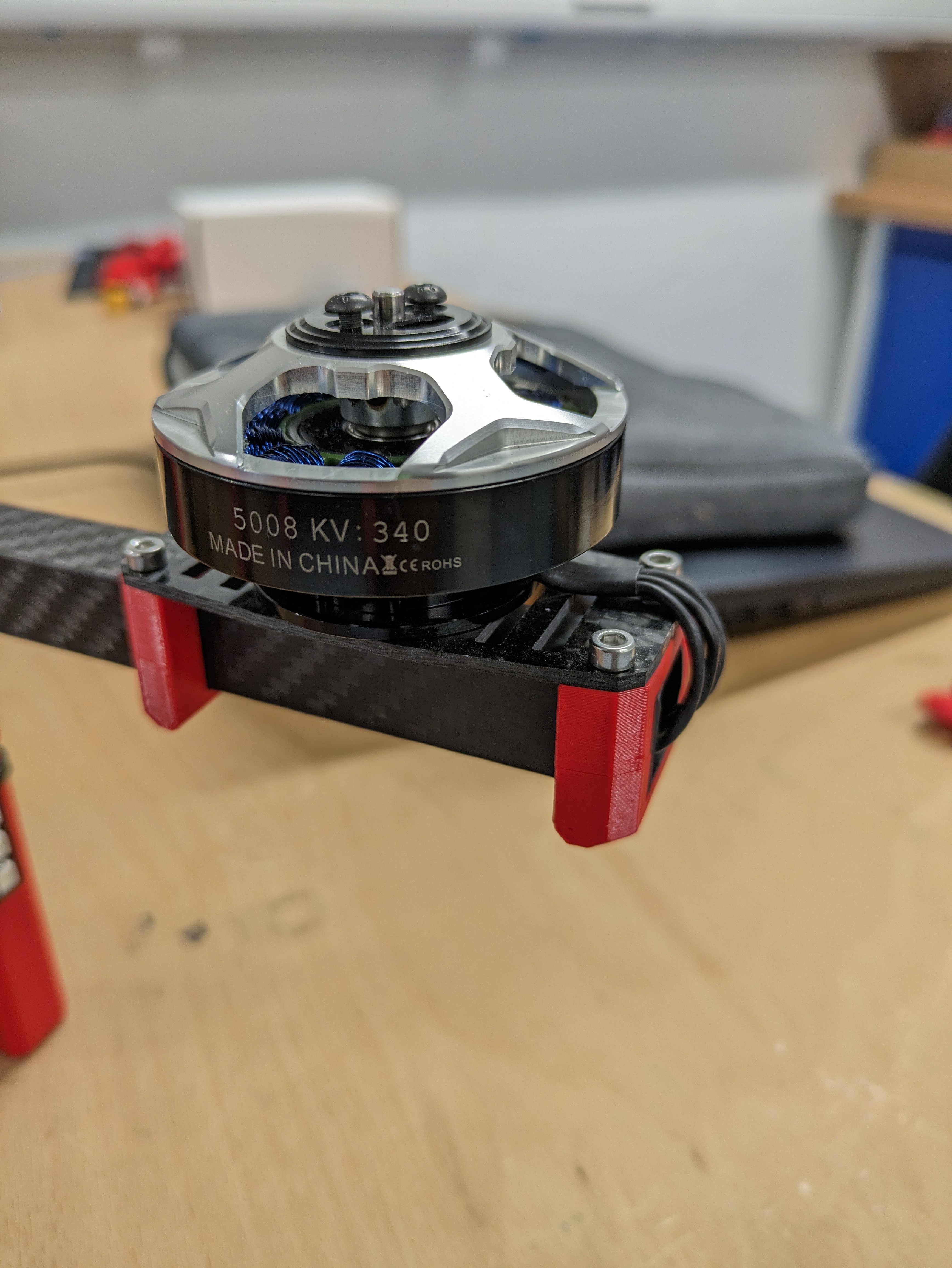
- Motor: Tarot 5008 340KV
- GPS: Matek M10Q-5883
- RC receiver: TBS Crossfire Nano
- Telemetry radio: SiK Telemetry Radio V3
- FPV system: Walknsail Avatar HD V2
- Battery: Turnigy 5000mAh 6S 40C LiPo
Designing the motor mounts
The Tarot 5008 motor has 4 3mm mounting holes situated evenly along a circle with a diameter of 25mm. 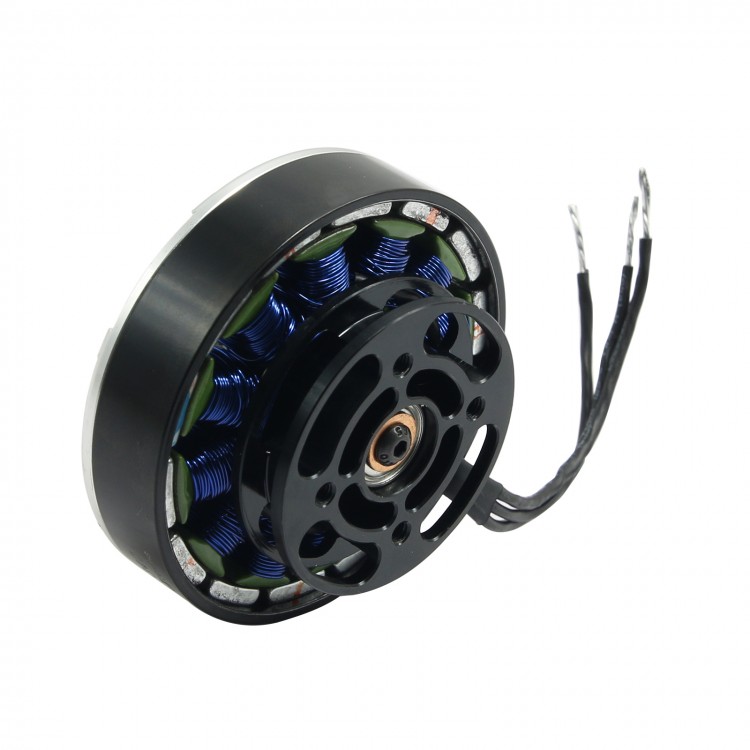 The arm which supports the motors will be a 16x16mm carbon fibre box section which is 400mm long.
  At the end of the arm, there will be a 3D printed mount which connects a carbon fibre plate to the motor arms, with the motor mounting to the carbon fibre plate. Since the motor wire ends in an MT60 connector, we are unable to drill holes through the carbon motor arm as this will stop the connector from passing through, hence we must rely on a clamping friction to keep the motor arm in place.
 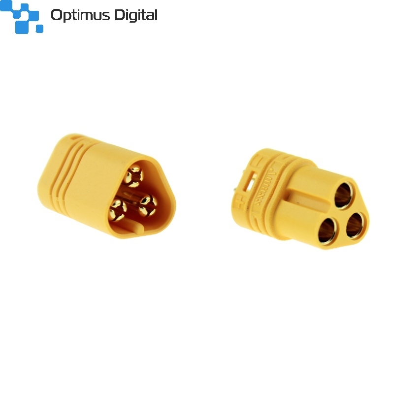 We can do this by creating a top and a bottom 3D printed clamp where a screw can secure the carbon plate together with the brackets clamping everything on the motor arm. As the screw head is 3mm tall for an M3 socket cap screw, we must ensure that there is at least 3mm of clearance between the carbon plate and the motor arm. To be able to use a screw to clamp the parts together, we need to add a brass heat-set insert into the print to add a thread which the screw can screw into.
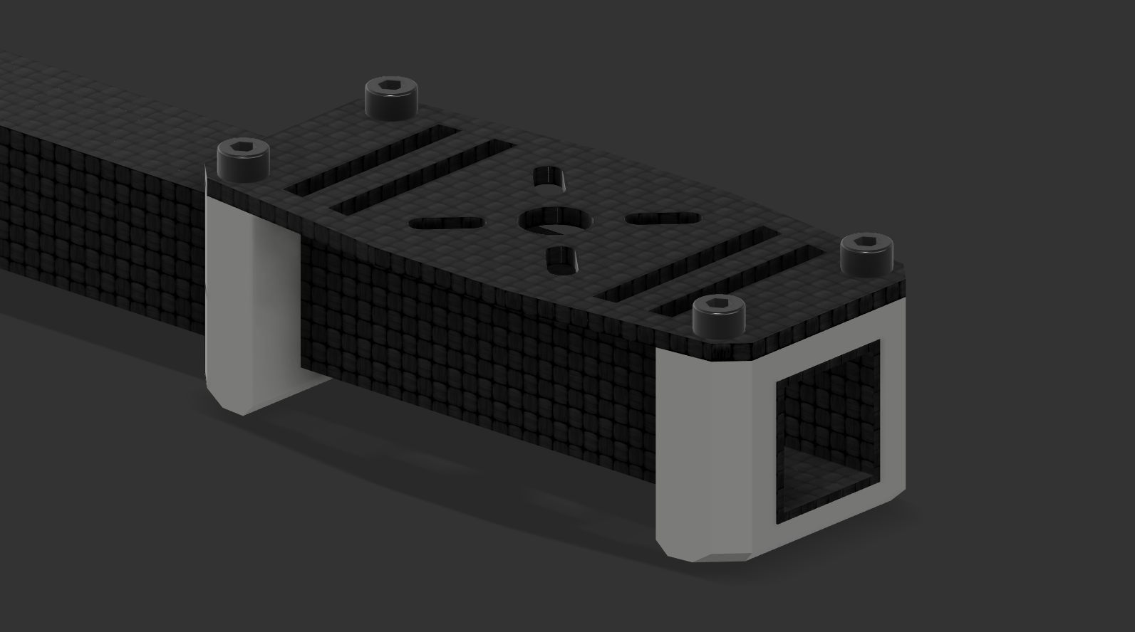
Motor mounting plate
With all of the design constraints written down, I then designed the motor mount plate on CAD, which the motors will attach to.  Instead of making holes for the motor screws, I chose to make slots so that in the future, if needed, the motor can be switched out for one with a different mounting arrangement.
3D printed mounting brackets
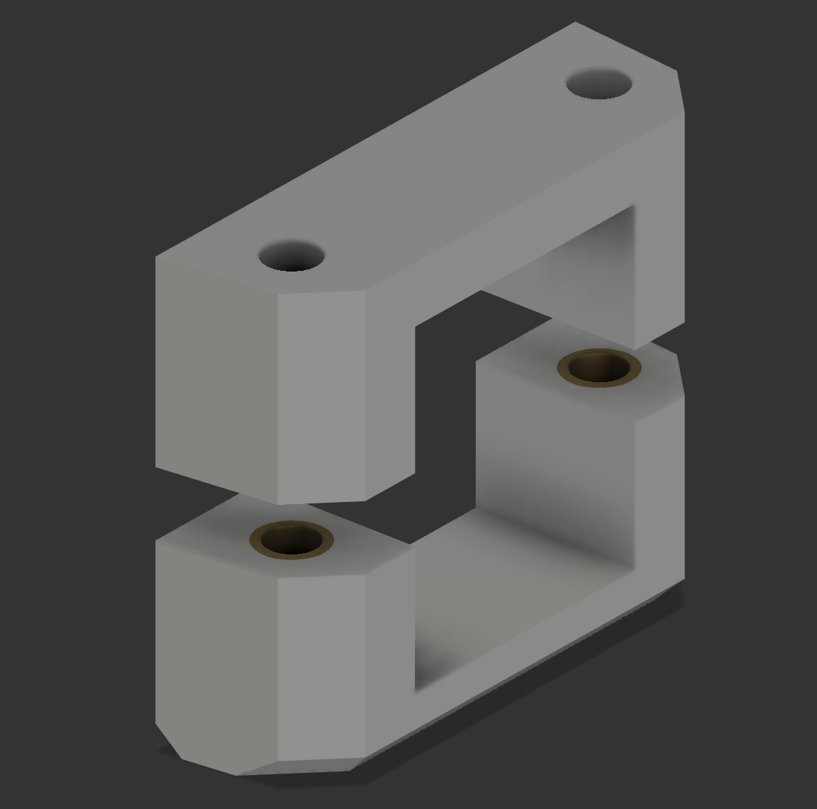
The mounting brackets which clamp the motor mount assembly to the motor arm are very simple; a simple 2-piece clamp is held together by screws threading into a brass insert within the bottom clamp. However, some design considerations should be made.
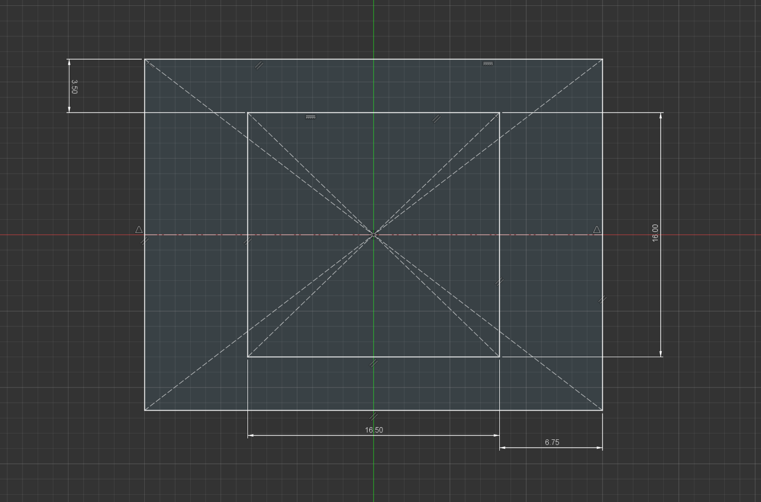
- Due to 3D printer tolerances, we should leave slightly extra room on the inside sides of the bracket as there is no need for a super tight clamp onto the motor arm from the brackets, in this case, I've made the width of the inner section of the clamps 16.5mm for a 16mm diameter motor arm.
- However, the vertical height of the inside of the bracket should be less as there needs to be a tight clamp from the top to bottom of the motor arm, hence in this case I've made the height 16mm exactly.
- Enough room needs to be left so the threaded insert can be properly set into the bracket and has a strong enough bond with the plastic. This will be dependent on which inserts you use.
Finished motor mounts
Designing the folding motor arm mechanism
The concept of the folding motor arm was inspired by the Tarot XS690 foldable quadcopter. My idea is that the square carbon fibre motor arm slots into a 3D-printed bracket and is locked in place with a screw going through it. The bracket is then secured to the airframe at a central pivot point which allows the motor arm to rotate. Then at the extended and folded positions, there are stopping brackets that stop the further rotation of the motor arm and lock it in its place.
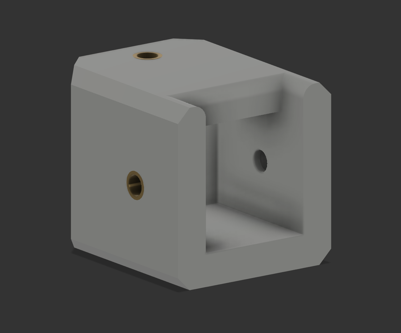
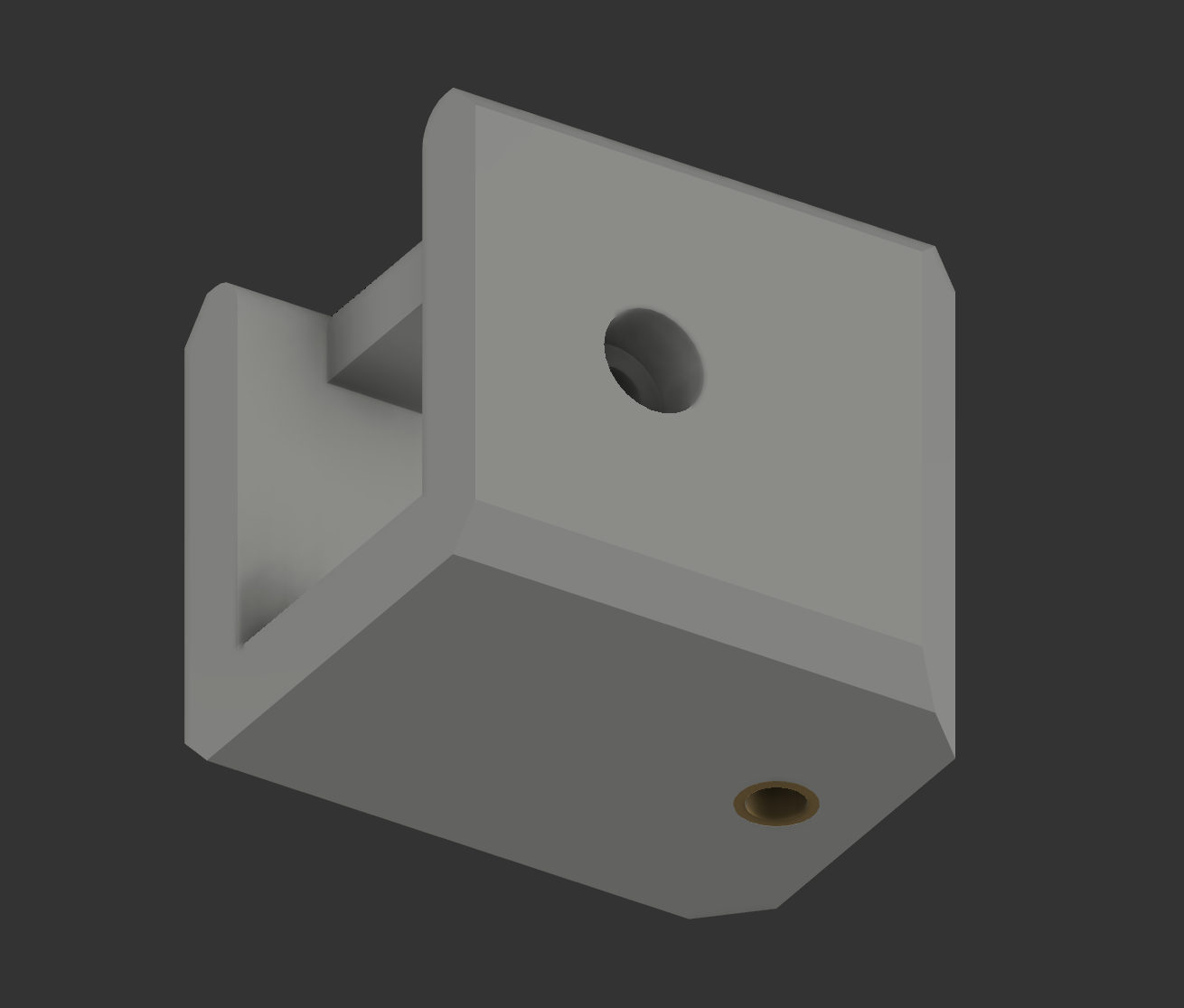
End cap
The end cap is the 3D printed bracket which allows the entire motor arm to rotate. Two screws will hold it to the top and bottom plates of the airframe and one screw will go through the carbon fibre motor arm to attach the arm to the end stop securely. All screws will thread into heat-set inserts. The tolerance given to the space which the motor arm slots into is 16.5mm on all sides as there isn't a need for a super-tight fit; the screw will hold the arm and end cap together not a friction fit. However, it's important to note that the height of the end caps will determine the distance between the top and bottom plates of the airframe.
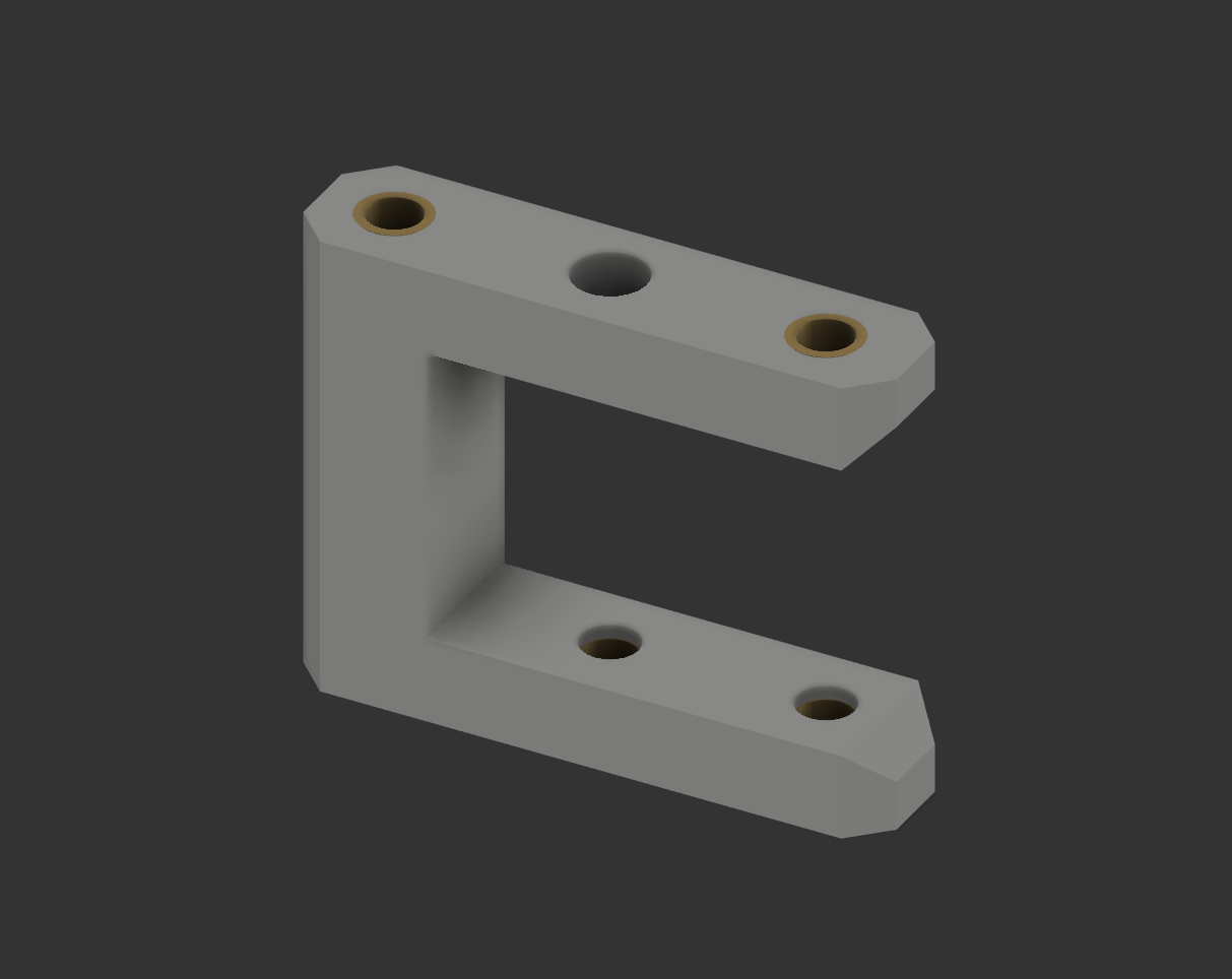
Stop brackets
The main purpose of the stop brackets is to stop the over-rotation of the motor arms when extending or folding them. They have two other purposes though; to lock the motor arm in place and to support the arm so it doesn't droop down from the end cap. The bracket is shaped as a C, which allows the motor arm to slide in from one direction but stops it from moving once it reaches the wall. To secure the bracket to the airframe, two screws hold it in place with the top and bottom plates with heat-set inserts. To lock the motor arm in place, a screw can be put through the airframe, through the bracket, through the middle of the motor arm and threaded into a heat-set insert at the bottom of the stop bracket. Designing the stop brackets symmetrically means that I don't have to worry about which orientation the bracket is in before adding the heat-set inserts, I just need not add an insert into one of the middle holes of the bracket (you could add an insert to the top hole but I didn't see much point in that).
Finished motor arm folding mechanism
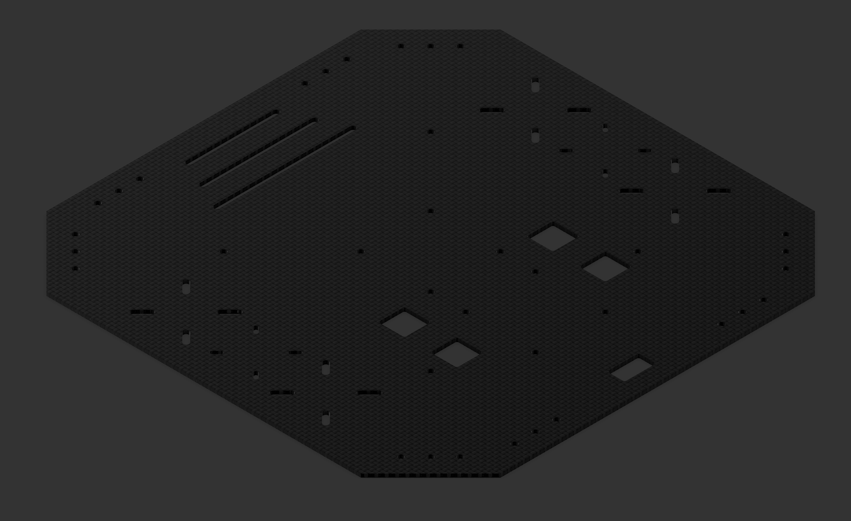
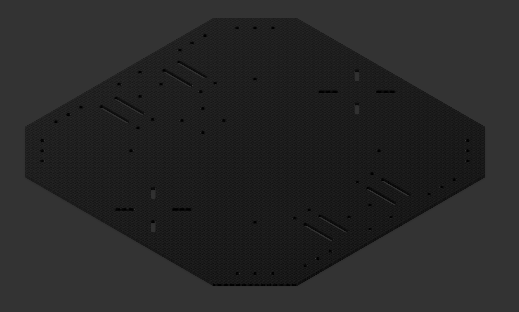
Designing the airframe
The airframe for this quadcopter simply consists of two carbon fibre plates. The motor arm end caps and stop brackets will be sandwiched between both of these plates. A spare Tarot battery mount from an old Tarot XS690 quadcopter will be mounted to the bottom plate to attach the battery. The idea is to replace this with a custom battery mounting plate which also allows for external payload attachment points. With the motors being able to support up to an 18" propeller, I decided that an appropriate size of the airframe would be 260x260mm. This leaves ample space for future avionics that can be added on, following this decision, I also ensured that there were extra mounting holes of multiple sizes available. In an attempt to keep wiring as neat as possible, I added 4 holes for the motor wires to go through from the ESC and 1 hole for the XT-60 connector which connects the ESC to the PDB on the bottom plate.
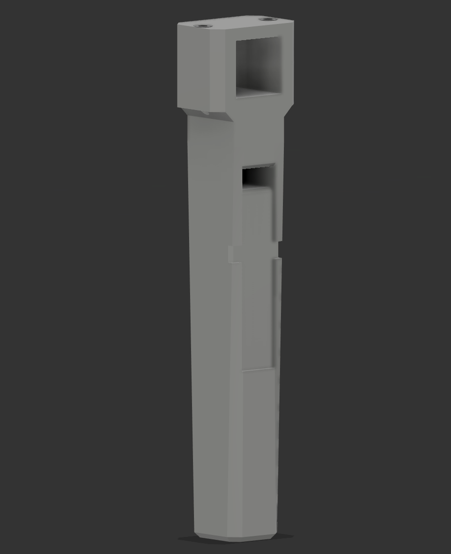
Designing the legs
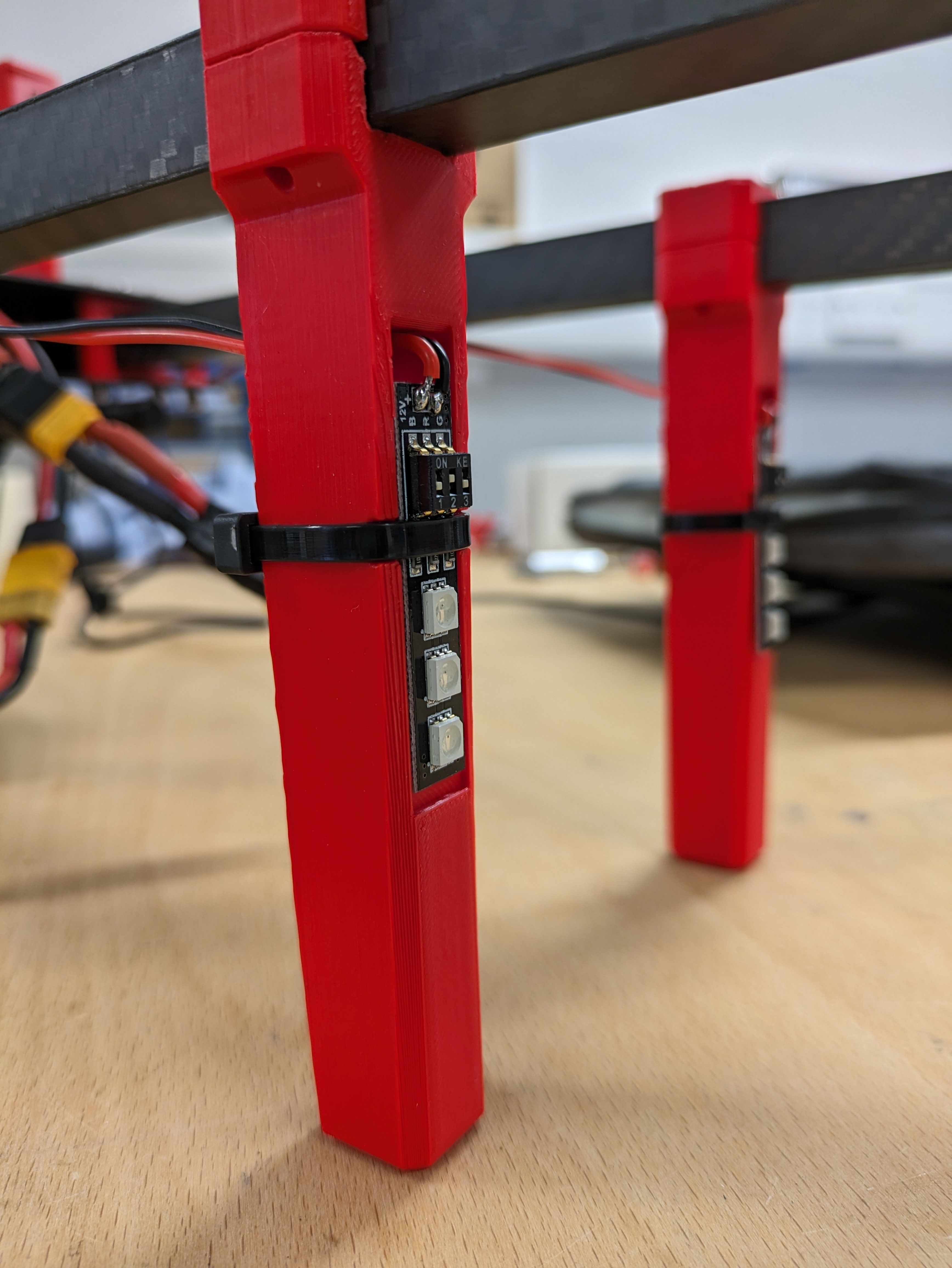
A lot of the quadcopters I've worked with have legs stemming from the airframe, however, for this quad, I wanted to create legs that were mounted to the motor arms, giving a wider (and hopefully more stable) landing base. The idea for the legs was to use a similar clamping method as the motor arms. One other requirement I had for the legs was to attach a small Matek RGB LED board. 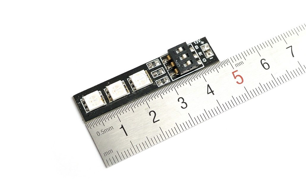 For attaching the board to the legs I thought just using a simple zip tie would do the job, but, I wanted the cable of the board to be routed nicely through the leg. That's why I decided to emboss an outline of the board on the front of the leg and create an opening above which would allow the board to pass through and sit on the front face. A zip tie would then attach the board to the leg.
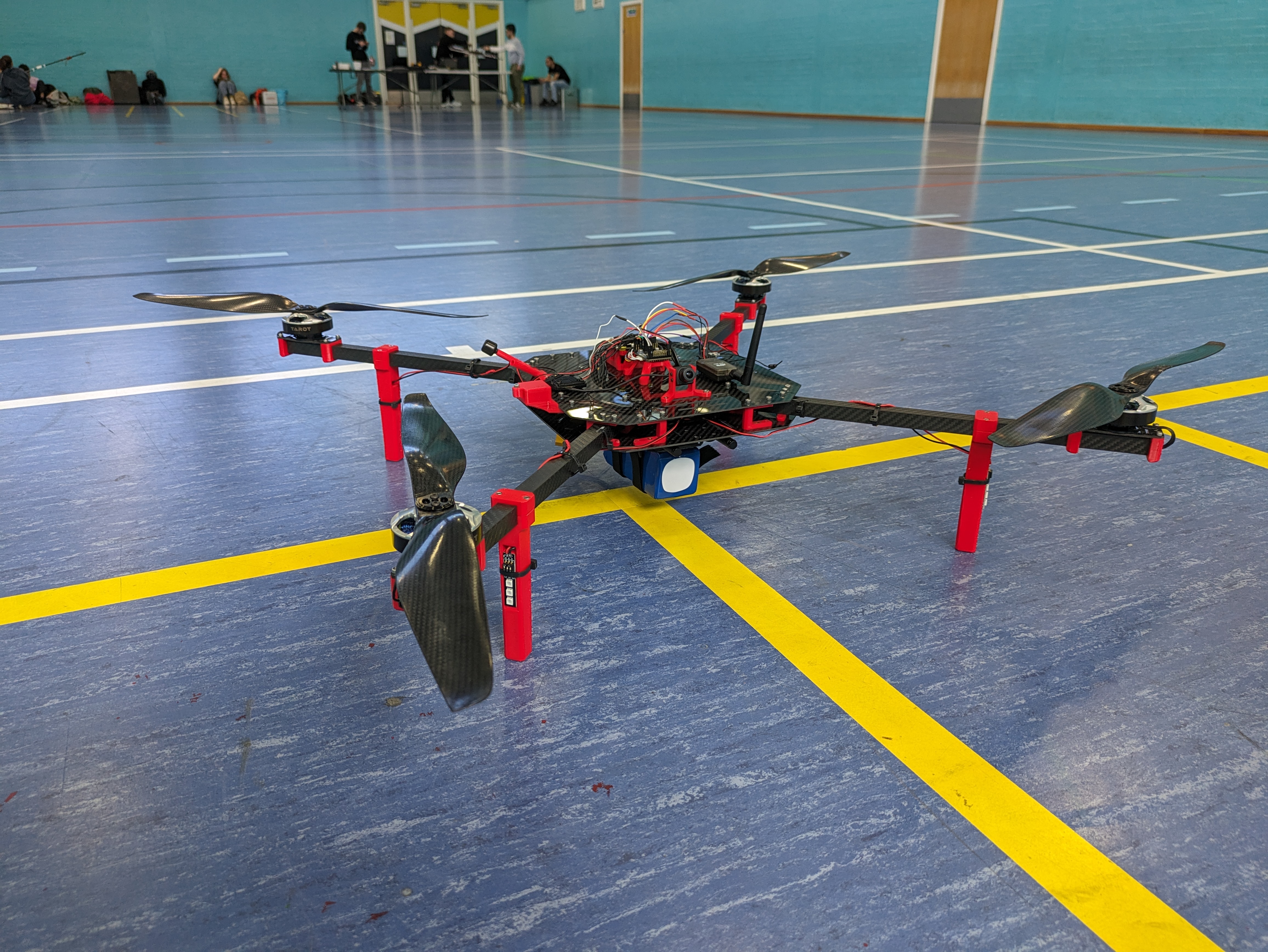
Finished build
I'm quite pleased with the end result. The airframe is quite rigid, the short and wide-spread legs provide a very stable base and the folding mechanism works perfectly. Looking forward to flying this drone soon!